by Matt Bush, on Aug 19, 2019 2:27:55 PM
When using waypoints in the UR programming as features you have to be aware of how the points are oriented and how the tool will approach the point. This applies no matter how you have created the waypoint and stored it, as a Feature using the built-in UR tools or an installation variable or just as a waypoint in your program.
Understanding Waypoints, Position and Orientation
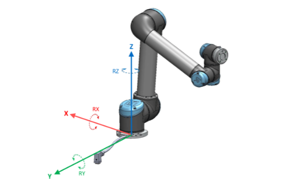
The first thing to realize is that all waypoints for UR contain two pieces of information, the first is the X, Y Z position of the TCP relative to the base of the robot and the other is the RX, RY and RZ orientation of the point (tool) relative to the base frame. The position is pretty straightforward to understand as its literally the position of the point in 3D space relative to the center flange of the robot base (assuming you have not modified any mounting settings). So the power cable is the +Y axis and +Z comes out the top of the base joint, opposite the surface that the robot is mounted against. This is detailed in the image below courtesy of Universal Robots.
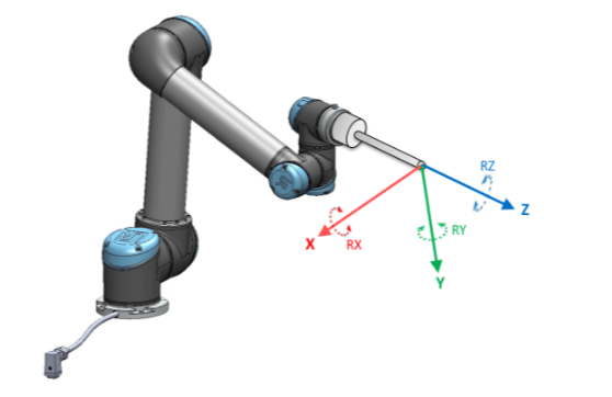
Here is where it gets a bit tricky, that the rotation is how the TCP is oriented relative to the base. So if I created a point at (0.1, 0.1, 0.1) and then oriented the Z axis to align with the Z axis of the base, i.e. pointing straight up then when I told the robot to move there it would align the TCP with the base Z axis and go to the point and make the arm flip upside down. This is because the Z-Axis of the tool is coming out of the flange of the tool and would want to align orientation with the pose of the position. See the image below courtesy of Universal Robots showing how the tool frame of reference is positioned, note in this image there is a tool installed, default TCP has all coordinates on the end of the robot flange with +Y pointing away from the tool IO point.
Remember waypoints have both position and orientation stored in the 6 dimensional pose, p[0,0,0,0,0,0] where a pose in Universal Robots programming is represented as p[x,y,z,rx,ry,rz]. One thing to always remember is that the tool is going to align with the orientation of the point so that all 3 axes will align with the axes of the point that is being used. This will make sense after we discuss the next point.
Built-in Plane Feature Pitfalls to Avoid
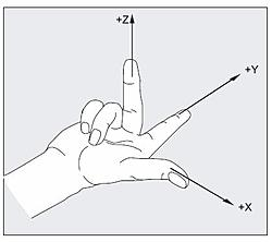
When you use the built-in feature tool for creating a plane you are defining the X and Y axis of the plane. Side note, older Polyscope versions had you teach Y axis as the primary axis but since the e-series came out this has flipped to X axis as being primary but this doesn’t matter for the example or explanation. For this explanation I am going to use the newer Polyscope methodology. When you teach a plane the first point that you teach is the home point of the plane and then the second point will define the +X axis of the plane. The third point you teach defines the direction of the +Y axis (flip these axes for older Polyscope versions). Since we now know the +X and +Y directions of the plane the right hand rule will tell us which way the Z Axis points. Align your thumb with +X and first finger with +Y (finger and thumb at 90 degrees), your curled second finger will point at +Z. This is a very handy tool that we use everyday with programming robots.
This is the critical one as this determines from which side we approach the plane. Just because I taught a flat plane on a table with the tool flange pointing down does not mean that is how the robot will approach the plane point when running a program. So if in my plane that I taught the Y axis goes away from me and the X axis points to my right then the tool will approach the point from under the plane as that is the direction that +Z is pointing.
Fixing issues with Approaching the Plane
This can be rectified in one of two ways. The first method is to teach the third point on the other side of the X axis so that the +Y axis is pointing at me and the +X axis is still pointing to my right, now when I apply the right hand rule the +Z axis would be pointing at the floor and not the ceiling. The second method would be to use pose_trans and rotate the plane 180 degrees around either the X or Y axis, depends on which axis you want to keep original. Then you would use the modified plane in all of your pose math of motion to have the tool approach from the correct direction.
Using Stored Waypoints
When you are using a single waypoint that was taught with the robot, there is generally not an issue with orientation since the pose that was stored was created by querying the actual robot position and then storing it. This is the same if I am using a Point Feature, a taught waypoint under a move or a pose stored as an installation variable. Where it can get a little tricky is if I created the waypoint through some other means such as doing pose math off a taught feature such as a plane. Then the point inherits the orientation from the feature that I am using. So for instance if I have a plane variable called Plane1_var and want to go to a point that is 100mm in the +x direction I could do the following math with the URScript language.
local pickPoint = pose_trans(Plane_1var, p[0.1,0,0,0,0,0])
I could then use pickPoint in a move command by either selecting variable as the type of waypoint from a polyscope waypoint screen or in URScript by typing something like this.
movej(pickPoint, a=d2r(80), v=d2r(60))
If my orientation was upside down because the plane I taught has +Z going in a direction 180 degrees from where I want it to be my motion will try to flip the robot hand upside down and approach from the side opposite where I wanted it to approach. To correct this I could change my pickPoint math to be the following:
local pickPoint = pose_trans(Plane_1var, p[0.1,0,0,0,d2r(180),0])
That will flip the orientation of my new point 180 degrees from the plane without affecting the actual plane variable.
Wrap Up
When defining the motion that you want the robot to follow its important to remember that the waypoints you are creating are made up of two elements, the position, 3D position in space relative to the base, and the orientation, a 3D representation of how the end-of-arm will be oriented relative to the base of the robot. Once you get these concepts down it becomes much easier to define more advanced motion and be confident the robot will do what you want.
I hope that this guide helped you to understand how waypoints store both position and orientation and how to use those points using Universal Robots programming. Stay tuned for more information and let me know if there is a topic that you would like to have covered.